
All cinema projectors employ light sources, optics, and a method of modulating light, in the manner shown below. Where projectors differentiate most is in the technology employed for the formation of images, referred to generically as spatial light modulators.
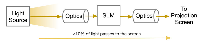
Figure P-11. Projector Light Path
Two different technologies of spatial light modulators are employed in cinema projectors: DLP micromirror technology from Texas Instruments (TI), and SXRD liquid-crystal-on-silicon (LCOS) technology from Sony Electronics. These technologies work in fundamentally different ways.
DLP modulates light in a temporal binary fashion, producing true digital modulation of light. Modulation takes place by oscillating one micromirror per pixel. Each micromirror either reflects light to the lens of the projector, or not. The micromirrors oscillate at rates up to tens of thousands of flips per second. By flipping the mirror back and forth, or not, a prescribed number of times per frame, a color shade is determined. The principle is illustrated below.
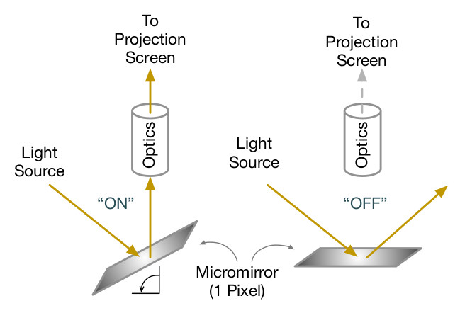
Figure P-12. TI DLP Light Path
SXRD LCOS operates in an analog fashion. Light is pre-polarized prior to passing through a polarizing beam splitter and toward an array of liquid crystal cells backed by a reflector. The SXRD LCOS device will change the light orientation which is determined through the application of an electric field. The SXRD LCOS electric field is updated once per frame. This polarized light is reflected back to the beam splitter which includes its own polarizer oriented 90 degrees to the SXRD LCOS device. The interference between light orientation from the SXRD LCOS device and the beam splitter polarization modulates the light output. The principle is illustrated below.
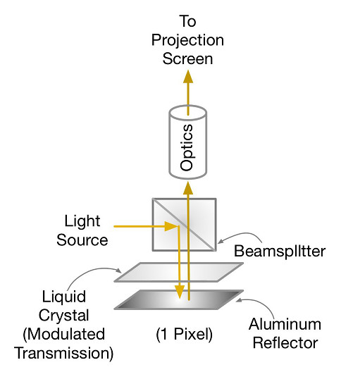
Figure P-13. SXRD LCOS Light Path
(Thanks to Gary Mandle for contributing the description of SXRD LCOS.)
Projectors are not efficient in the utilization of light, transmitting less than 10% of light from the light source to the screen, as indicated in the figure at the top of this section. In addition, the presence of infrared light in the light source will result in heat retention in light modulators and optics, which must be dissipated. Future projection systems will target improvements in each of these areas.