
- Color
- Contrast
- Resolution
- Light
This chapter sets out to discuss each factor and its contribution to the cinema experience. Also discussed are the technologies that present picture in cinema.
The Technology Behind The Big Screen
section-1077

This chapter sets out to discuss each factor and its contribution to the cinema experience. Also discussed are the technologies that present picture in cinema.
section-1079

Color values in digital cinema are distributed in the form of tristimulus values of red, green, and blue (R, G, B). The container color space referenced by the RGB values is a normalized form of the CIE XYZ color space, defined in SMPTE ST 428-1 Image Characteristics and referred to as the X’Y’Z’ color space. Container color space refers to the reference color space in which the RGB values are encoded. In practical terms, this means that the X’Y’Z’ color values in digital cinema distributions can describe any color visible to the human eye. The practical limits of color in cinema, as a result, are entirely determined by the display device. This has future value to cinema in that the distribution data format can readily accommodate emerging projectors and displays having wider color gamuts.
With the limits of color entirely determined by the display, the display requires special attention. Cinematographers and colorists need to know the minimum set of colors that will be correctly reproduced in the cinema. The answer to this is the establishment of a minimum display color gamut required of all digital cinema projectors and displays. This minimum display gamut is referred to as DCI-P3. The name derives from the original definition by DCI in its Digital Cinema System Specification v1.0 (2005). DCI-P3 is now codified in SMPTE RP 431-2 Reference Projector (although the Recommended Practice does not name the color gamut.) The ability to reproduce the full P3 color gamut, using Composition color values encoded in X’Y’Z’, is a requirement of DCI-compliant projectors and displays. (The DCI-P3 color space is illustrated in the next section.)
Digital cinema is unique in its clear separation of color management roles for distribution and for display. For the scheme to work properly, the X’Y’Z’ color values in the Composition must be transformed to the actual color space of the projector or display. This requires real-time computation within the display device. In practice, to ensure color accuracy, the color primaries of the projector or display are measured by a technician and entered into the color transform engine. Incoming X’Y’Z’ color values are then transformed to the color space determined by the actual primaries of the projector or display. (See the illustration below.) The result is the preservation of color, as the colorist intended, on cinema screens everywhere.
It must be noted that this level of color precision is only available in digital cinema, and is not available in home entertainment. Maybe, one day, that will change.
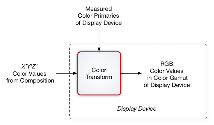
Figure P-0. Color Transformation in Cinema
section-1387

The minimum color gamut in standard digital cinema is DCI-P3. However, wider color gamuts than DCI-P3 are now possible. To better understand how wider color gamuts affect perception, several CIE chromaticity diagrams are shown below, beginning with Pointer’s Gamut.
Michael R. Pointer published in 1980 a maximum gamut for real surface colors, based on 4089 samples, establishing a widely respected target for color reproduction. Visually, Pointers Gamut represents the colors we see about us in the natural world. Colors outside Pointers Gamut include those that do not occur naturally, such as neon lights and computer-generated colors possible in animation. Pointers Gamut is illustrated below.
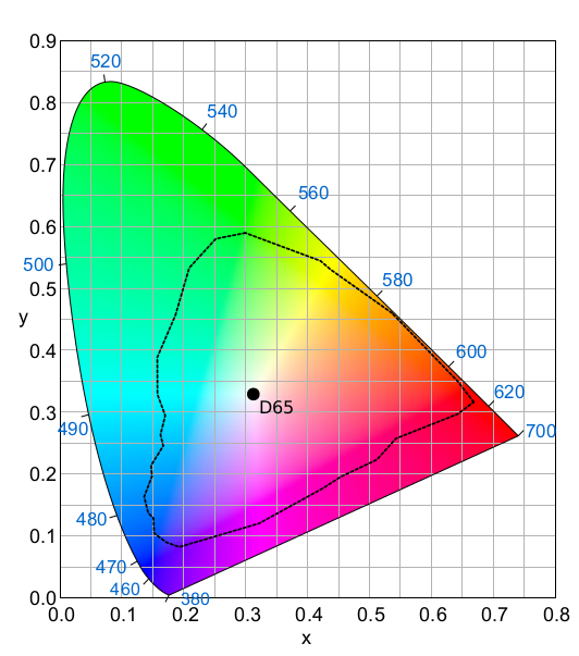
Figure P-1. Pointers Gamut
Rec. 709 is the ITU Recommendation for HDTV. Included in the Recommendation is the HDTV color space, also known as “Rec. 709.” The Rec. 709 color space is compared with Pointers Gamut, below. As can be seen, the Rec. 709 color space is significantly smaller than Pointers Gamut, which is why it was deemed unsuitable for digital cinema.
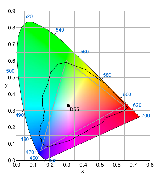
Figure P-2. Rec. 709 Color Space Compared With Pointers Gamut
DCI-P3 is the minimum color gamut required of digital cinema projectors and displays. Emphasis should be placed on P3’s role as the minimum color gamut for cinema display, as it is not the container color space for digital cinema. (This is discussed in more detail in the prior section.) The P3 color gamut was first specified by Digital Cinema Initiatives (DCI) in its Digital Cinema System Specification v1.0 (2005), and is now documented in SMPTE RP 431-2 Reference Projector.
Below, DCI-P3 is compared with Pointer’s Gamut. As you can see, DCI-P3 covers most of Pointers Gamut.
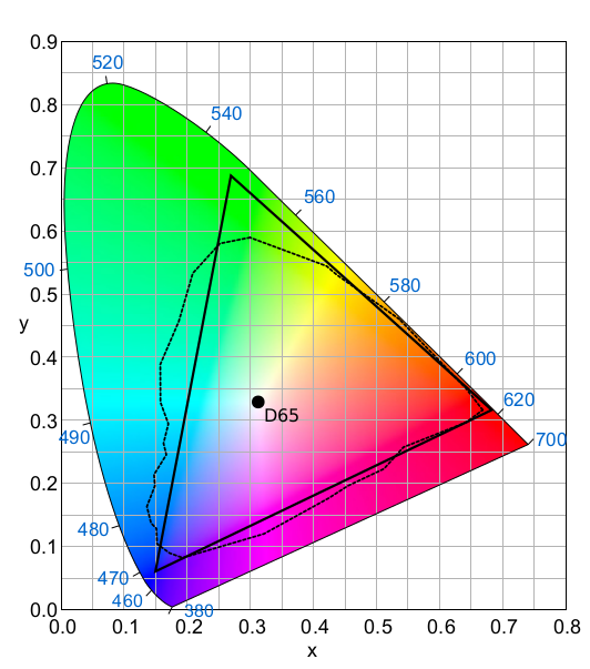
DCI-P3 compared with Pointers Gamut
Rec. 2020 is the ITU Recommendation for UHDTV. Included in the Recommendation is the UHDTV container color space, commonly known as “Rec. 2020,” designed to incorporate Pointers Gamut. However, emphasis must be placed on the word “container,” as practical displays cannot implement Rec. 2020. The actual implementation of Rec. 2020 in a display requires nanometer-wide primaries only possible with lasers, which would lead to metameric problems and speckle. (Metameric problems can result in a lack of color agreement among multiple viewers. Speckle is often seen in the speckled pattern of laser pointers.) Unlike digital cinema, the ITU does not define a minimum UHDTV display gamut to guide manufacturers and artists.
The illustration below is of Rec.2020 compared with Pointers Gamut and DCI-P3. Note that if a wider minimum display gamut than DCI-P3 were to emerge, the primary benefit would be improvement in the cyan range. Deeper cyans will deliver more vivid color in ocean shots, for example.
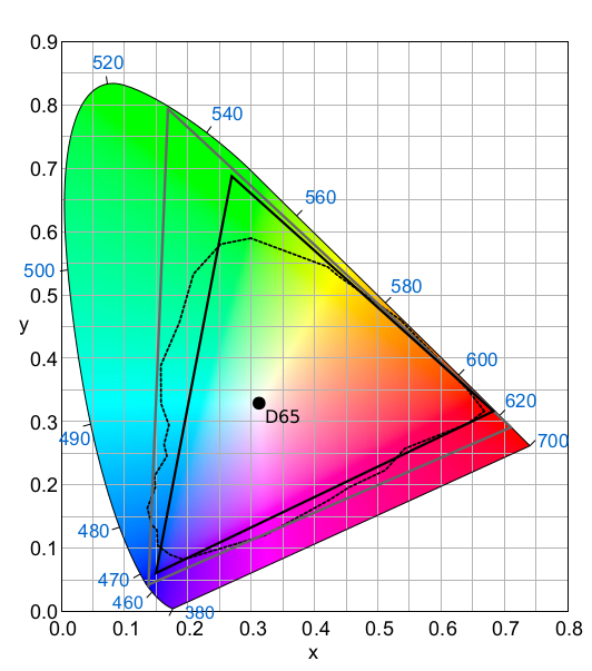
Figure P-3. Rec. 2020 (light grey) compared with Pointers Gamut and DCI-P3
For those who are interested in learning more about color gamuts and color encoding, NVIDIA provides an excellent tutorial on the subject in (the first 17 pages of) its paper UHD Color For Games, authored by Evan Hart.
section-1089

Image contrast and dynamic range in a projector or display refer to the ratio of brightest white to deepest black. These parameters can be a useful measure of image quality, but are not the only factor for determining quality.
The two images below are examples of good contrast and low contrast. A histogram is included with each photo to bring attention to the visual impact of high black level in low dynamic range displays. (The low end of the “X” axis represents black level.) The images underscore the importance of deep blacks in addition to peak whites in displays. Simply increasing brightness of a low dynamic range projector or display will wash out the image, a concern that is particularly important when displaying High Dynamic Range (HDR) content.

Figure P-4. High Contrast

Figure P-5. Low Contrast
Contrast is measured in multiple ways. Sequential contrast is defined as the ratio of peak white to black, and tends to be limited by the image formation technology of the projector or display. Intra-frame contrast is measured using a checkerboard pattern, and can be impacted by numerous optical anamolies, such as lens flare or even port glass flare. SMPTE RP 431-2 Reference Projector calls for a nominal ratio of 2000:1 for sequential contrast in projectors, with a minimum 1200:1 sequential contrast for cinemas. The SMPTE Recommended Practice also calls for a nominal intra-frame contrast of 150:1, with a minimum 100:1 intra-frame contrast for projectors in cinemas.
SMPTE RP 431-2 Reference Projector is a useful reference for many parameters concerning picture presentation, including the cinema reference white level of 48 nits and reference white chromaticity coordinates.
It should be mentioned that the contrast numbers quoted above target standard cinema picture presentation, not HDR Cinema picture presentation. HDR standards for cinema have not yet emerged at the time of this writing. But HDR standards for home entertainment do exist. The UHD Alliance HDR10 specification sets two standards: (1) more than 1000 nits peak white and less than .05 nits black, and (2) more than 540 nits peak white and less than .0005 nits black. Specification (1) has a sequential dynamic range of 20,000:1, while specification (2) has a dynamic range of 1,080,000:1.
As a step towards establishing appropriate light levels for HDR Cinema, the American Society of Cinematographers (ASC) released its Cinema Display Evaluation Plan & Test Protocol to guide future research.
section-1097

SMPTE ST 428-1 Image Characteristics specifies two classes of picture resolution: 2K and 4K. For each class of resolution, the standard defines the available container for the picture, as shown in the table below.
| Resolution | Maximum Horizontal Pixels | Maximum Vertical Pixels |
| 4K | 4096 | 2160 |
| 2K | 2048 | 1080 |
Table P-1. Picture Containers
Theoretically, any aspect ratio can be carried in the container, so long as the maximum horizontal or vertical pixel count is not exceeded. In practice, however, cinemas are set up to support only two aspect ratios. The “scope “aspect ratio, which is 2.39:1, is centered in the container with maximum width. The “flat” aspect ratio, which is 1.85:1, is centered in the container with maximum height. The image sizes for scope and flat aspect ratios are shown in the table below.
| Resolution | Aspect Ratio | Horizontal Pixels | Vertical Pixels |
| 4K | Scope 2.39:1 | 4096 | 1716 |
| 4K | Flat 1.85:1 | 3996 | 2160 |
| 2K | Scope 2.39:1 | 2048 | 858 |
| 2K | Flat 1.85:1 | 1998 | 1080 |
Table P-2. Picture Resolutions
Resolution is recognized as an important quality of digital images. But the human perception of resolution is limited by visual acuity. Good vision is defined as that capable of discerning an object at a visual angle of 1 arc minute, or 1/60 of a degree. Using this information, the required seating position in relation to the screen can be calculated for discerning one pixel, as illustrated in the diagram below.
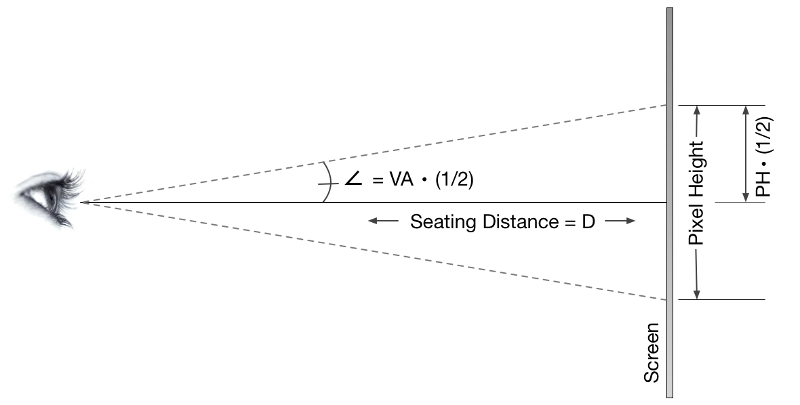
Figure P-6. Visual Acuity and Resolution
Applying trigonometry, the following equation can be derived:
tan (VA * 1/2) = PH / 2D
Where
In cinema, seating position is often referenced in terms of picture height, recognizing the geometrical relationship of seating position to screen. From the charts above, picture height of a 4K image is at most 2160 pixels. One pixel height, therefore, would be 1/2160 screen height.
Taking this into account, the formula for maximum viewing distance D is:
D = [1 /(2 * 2160)] / [ tan (VA * 1/2)]
Using this equation, D = 1.59 screen heights. In other words, the furthest seating position where a 4K image can be appreciated in full resolution is 1.59 screen heights from the screen. For a 2K image, the distance is twice that. To give this perspective, most cinemas place seats nearest the screen around the 1 screen height position. This leaves only a few rows where 4K resolution can be fully appreciated.
There is also audience preference to consider. The audience tends to prefer seating in the middle of the auditorium and not the front of the auditorium, where mid-auditorium is typically around 3 screen heights from the screen. The paradox of higher resolution imagery in cinema is that the seats that benefit most from higher resolution are not the seats that the audience values.
section-1154

When discussing picture presentation in cinema, it’s easy to overlook the light source itself. But as advancements in projection and display technology move away from traditional light sources, the quality of light deserves attention. Newer light source technologies are designed to produce less or no infrared light, for example. Infrared radiation heats optics and light modulators, and components in the light path benefit from cooler operation. Newer light technologies also trend towards power reduction and substantial improvements in longevity, reducing operating costs. But along with the benefits come challenges that demand more insight into the nature of emerging light sources.
At its simplest, the goal of a light source is to reproduce the entire visible spectrum with a high degree of uniformity, as illustrated below.

Figure P-7. Full Spectrum (wavelength in nm)
Legacy light sources, such as the xenon lamps commonly found in projectors, produce a full spectrum of light with a high degree of uniformity across the spectrum. RGB primaries are developed by filtering this highly uniform light. The illustration below is representative of the concept.

Figure P-8. Filtered RGB Primaries (wavelength in nm)
Newer sources of light, however, do not generate full spectrum light. The most extreme example of a new generation light source is the laser illuminator. Laser light, by its very nature, is extremely narrow in bandwidth, often 1 nm or less. This can result in very narrow RGB primaries, as shown below.

Figure P-9. Laser RGB Primaries (wavelength in nm)
The illustrations above show the dramatic difference that can occur in the spectral content of newer light sources. These technologies take full advantage of the ability of human eyes to respond to tristimulus color representation. But with new benefits come new challenges. There are two well-known visual aberrations that accompany narrow-band primaries.
The first aberration is the visual phenomenon of metameric variability. The extremely narrow bandwidths of laser primaries do not always induce identical tristimulus response in human eyes. The result is disagreement among observers as to the colors projected or displayed on screen, an effect known as metameric variability. For some people, such disagreement can be disconcerting. In many cases, the absence of metamerism is experienced as a color cast in the image. While metamerism disagreements can occur with any light source, laser-illuminated projectors can greatly exacerbate the problem.
The practical way to address metameric variability is with wavelength diversity in the primaries. Xenon-filtered light presents the tried and true example, but wavelength diversity is possible with newer technologies, too. Note that it takes substantial diversity, beyond adding lasers a few nanometers apart, to mitigate metameric variability.
The second aberration is that of speckle. Laser light is coherent by design. Coherent light is extremely uniform in both directionality and frequency. When coherent light bounces off a screen, the reflected light interferes with the incident light, causing peaks and valleys of intensity, or speckle. The effect is captured in the animation below.

Figure P10. Laser Speckle (source: LaserPointerSafety.com)
There are several known techniques for eliminating speckle, including angle diversity, polarization diversity, wavelength diversity, and simply shaking the screen. Of these methods, the only one capable of mitigating both speckle and metameric variability is wavelength diversity.
section-1143

The Digital Cinema Picture Track File is defined in SMPTE ST 429-3 Sound and Picture Track File. The standard defines a constrained application of SMPTE ST 390-2011 MXF Pattern “OP-Atom”, requires compliance with SMPTE ST 379 MXF Generic Container, and requires compliance with SMPTE ST 377 MXF File Format Specification.
The Picture Track File is compressed using JPEG 2000. The JPEG 2000 profile for digital cinema is defined in ISO-IEC 15444-1. JPEG 2000 employs a Discrete Wavelet Transform for compression. Each frame is compressed independently of other frames, a technique known as intraframe compression. JPEG 2000 is scalable in nature, where each compressed frame carries multiple resolutions of the image. Importantly, it is the multiple resolution feature of JPEG 2000 that allows a 4K or 2K image to be extracted from a single Picture Track File.
In practice, picture data from post production is converted to a series of still image frames using the Tagged Image Format File (TIFF), as constrained in SMPTE ST 429-4 DCP MXF JPEG 2000 Application.
Those seeking more information on the compression algorithm will find substantial resources on the web describing the Discrete Wavelet Transform and JPEG 2000.
section-1204

All cinema projectors employ light sources, optics, and a method of modulating light, in the manner shown below. Where projectors differentiate most is in the technology employed for the formation of images, referred to generically as spatial light modulators.

Figure P-11. Projector Light Path
Two different technologies of spatial light modulators are employed in cinema projectors: DLP micromirror technology from Texas Instruments (TI), and SXRD liquid-crystal-on-silicon (LCOS) technology from Sony Electronics. These technologies work in fundamentally different ways.
DLP modulates light in a temporal binary fashion, producing true digital modulation of light. Modulation takes place by oscillating one micromirror per pixel. Each micromirror either reflects light to the lens of the projector, or not. The micromirrors oscillate at rates up to tens of thousands of flips per second. By flipping the mirror back and forth, or not, a prescribed number of times per frame, a color shade is determined. The principle is illustrated below.
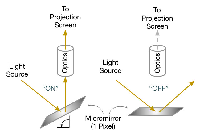
Figure P-12. TI DLP Light Path
SXRD LCOS operates in an analog fashion. Light is pre-polarized prior to passing through a polarizing beam splitter and toward an array of liquid crystal cells backed by a reflector. The SXRD LCOS device will change the light orientation which is determined through the application of an electric field. The SXRD LCOS electric field is updated once per frame. This polarized light is reflected back to the beam splitter which includes its own polarizer oriented 90 degrees to the SXRD LCOS device. The interference between light orientation from the SXRD LCOS device and the beam splitter polarization modulates the light output. The principle is illustrated below.
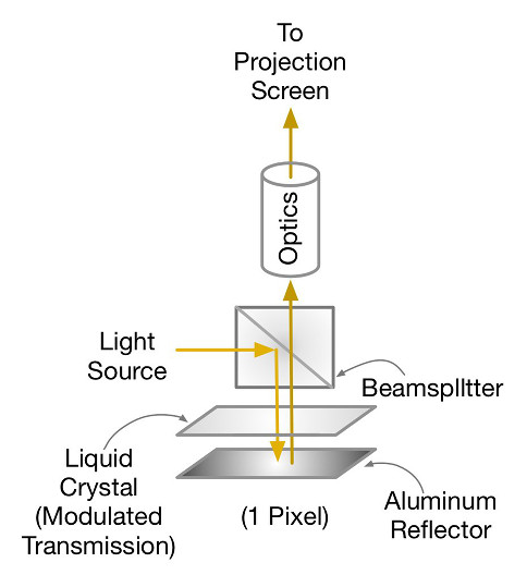
Figure P-13. SXRD LCOS Light Path
(Thanks to Gary Mandle for contributing the description of SXRD LCOS.)
Projectors are not efficient in the utilization of light, transmitting less than 10% of light from the light source to the screen, as indicated in the figure at the top of this section. In addition, the presence of infrared light in the light source will result in heat retention in light modulators and optics, which must be dissipated. Future projection systems will target improvements in each of these areas.
section-1211

The projection screen is the technology upon which the projected image is formed. As obvious as that may sound, it is an under-appreciated art. Projection screens provide diffuse reflection of light towards the audience. Depending on design and environment, they may also reflect unwanted light to the audience. The screen properties system designers pay attention to are gain, angle of view, and preservation of polarization.
Screen gain and angle of view are interdependent properties. An ideal screen, having a gain of 1.0, reflects light uniformly over a 180 degree dispersion pattern. A screen with “gain” does not manufacture light to produce the gain, as the word might imply, but concentrates the reflected light in a more narrow dispersion pattern to effectively deliver a higher percentage of projected light to the audience. The higher the gain, the smaller the angle of view.
Projection screen manufacturers have developed numerous proprietary methods to narrow the angle of view and deliver gain. The challenge when developing such techniques is to deliver lambertian-like reflectance across the dispersion angle. The goal of screen designers is to avoid hot-spotting, the characteristic where the image is noticeably brighter along the line of sight.
Preservation of polarization is of concern with polarized stereoscopic 3D systems, where the projected light has a polarized characteristic critical to the selection of image seen by each eye. Lambertian reflectance does not preserve light polarization, which is why a different class of so-called “silver” screens is marketed for polarized 3D projection. Silver screens are coated with aluminum flakes, serving as the reflective polarization-preserving element. Silver-screens tend to be high gain screens, and may exhibit hot-spotting. A second class of polarization-preserving screens has also been introduced, based on the metallization of gaussian diffusers. The advantage of this technique is uniformity of light distribution while preserving polarization. Proper design of the gaussian diffuser can enable control of the diffusion angle, and thus gain, without hot-spotting. The difficulty of this technology, however, is the seaming of the material to create a screen of suitable size for cinemas.
High-gain screens are important when considering HDR projection. The graph below simulates a 60K lumen projector on a unity gain screen, depicting available light levels. It illustrates why it is hard to achieve high peak whites on large screens, such as those found in premium large format (PLF) cinemas. (The graph also depicts available light levels for the different configurations of 6-primary color-separated 3D projection.)
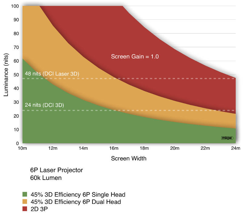
Figure P-14. Luminance Of A Unity Gain Screen With 60K Lumen Projector
All cinema screens, whether projection screens or emissive display screens, share certain challenges. Besides suffering the occasional abuse of patrons (a screen must be cleanable), there is the reflection of unwanted light to address. Unwanted light is any light other than that of the image, including ambient light from aisle lighting, auditorium exit lights, as well as the reflection of image and ambient light off the audience. When a screen reflects unwanted light, the effect is to degrade black level and contrast. This is a challenge for projection screens, whose purpose is to reflect light. It is for this reason that so-called “grey” screens were developed, having a gain of less than unity. Grey screens demand more light of the projector, but deliver higher contrast and deeper blacks through reduced reflection of unwanted light.
section-1243

3D became popular following the introduction of digital cinema in part because of its ability to operate with a single unmodified digital projector. The 3D effect takes advantage of the stereoscopic nature of human vision. A 3D production delivers a left-eye series of pictures, and a right-eye series of pictures. In practice, both sets of images are packaged in a single track file, as defined in SMPTE ST 429-10 DCP Stereoscopic Picture Track File. When packaging stereoscopic content, a stereoscopic frame pair is considered a single frame, with each frame carrying a left-eye and a right-eye image. In practice, stereoscopic content is normally played at a 48 frame-per-second (fps) rate, or 24 fps-per-eye. A stereoscopic package as such would be referred to as 24 fps 3D.
At the projector, the left-eye and right-eye images of 3D content can be processed sequentially or simultaneously. In order for the audience to correctly perceive the stereoscopic effect, left-eye images must be directed to the left eye, and right-eye images directed to the right eye. There are three techniques for performing this selection, all of which require the use of glasses.
The most straight-forward technique is that of shutter glasses. Shutter glasses are designed to allow light to pass to only one eye at a time. By synchronizing the shutter mechanism of the glasses with the playout of left-eye and right-eye images, the correct images are directed to each eye. The shutter process must take place quickly so as not to be detectable. To accomplish this, the sequential content is played using a technique called “double-flash” or “triple-flash.”
In triple-flash, left-eye and right-eye images are displayed sequentially by the projector at 3 times the rate of playout. (Double-flash requires 2 times the rate of playout.) When counting the linear image rate of 48 fps (2 x 24 fps), the projector displays 144 images per second. This is illustrated below for frames 0 and 1.

Figure P-15. Triple-Flash Sequential 3D
Another technique for selecting images when viewing is polarization. Circular polarization is the most common 3D selection technique found in cinema. The 3D polarizing element is placed after the projector lens, and the audience wears matching polarized glasses designed to select the appropriate image for each eye. For sequential 3D projection, the polarizing element is synchronized with the flash rate of the projector, changing the state of polarization according to whether the image being displayed is left-eye or right-eye. It is also possible to employ polarization with simultaneous 3D projection, where left-eye and right-eye images are displayed simultaneously. Simultaneous 3D projection is possible with dual projectors and specially configured single projectors.
A third technique for selecting stereoscopic images is color-separation, also known as spectral filtering. In this technique, image selection is performed by allowing the left eye to see one set of RGB primaries, while the right eye sees a different set of RGB primaries. This requires a single projector capable of generating 6 primaries (2 x R, 2 x G, 2 x B), or two projectors having two different sets of 3 primaries. Depending upon the projector configuration, left-eye and right-eye images can be projected sequentially or simultaneous. If sequentially, the images are flashed. The illustration below shows left-eye images being projected simultaneously using primaries RGB(L), and right-eye images projected using primaries RGB(R).

Figure P-16. Color-Separated 3D (shown for simultaneous 3D presentation)
All three methods are employed in cinemas, although the most popular system is polarization, due to the low cost of glasses and the ability to recycle glasses. Shutter glasses require active circuitry, powered by a battery, and cleaning after each use. Similarly, color-separating glasses require somewhat expensive filter coatings on the lenses, as well as cleaning after each use. It’s worth noting that 3D color-separation, using RGB laser-illuminated projectors configured with 6 primaries (6P), delivers the most light-efficient 3D of any of the techniques described.